

Solar EPC
Galvanized module mounting structures, cable trays and earthing for utility, rooftop and C&I solar.
What this sector needs
Solar EPCs source ground-mount and rooftop structures, channel trays and earthing from Vajra — galvanized to 25-year service and engineered to site wind and snow loading.
Product lines for this sector

Solar Panel Mounting Structures
Pre-galvanized and HDG module mounting structures, ground-mount, rooftop and tracker-ready, built for wind and snow loads.
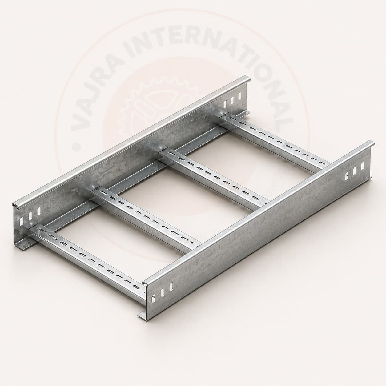
Cable Trays
Ladder, perforated, and raceway cable trays roll-formed in MS, GI, SS and aluminium, sized and finished to project load and environment.
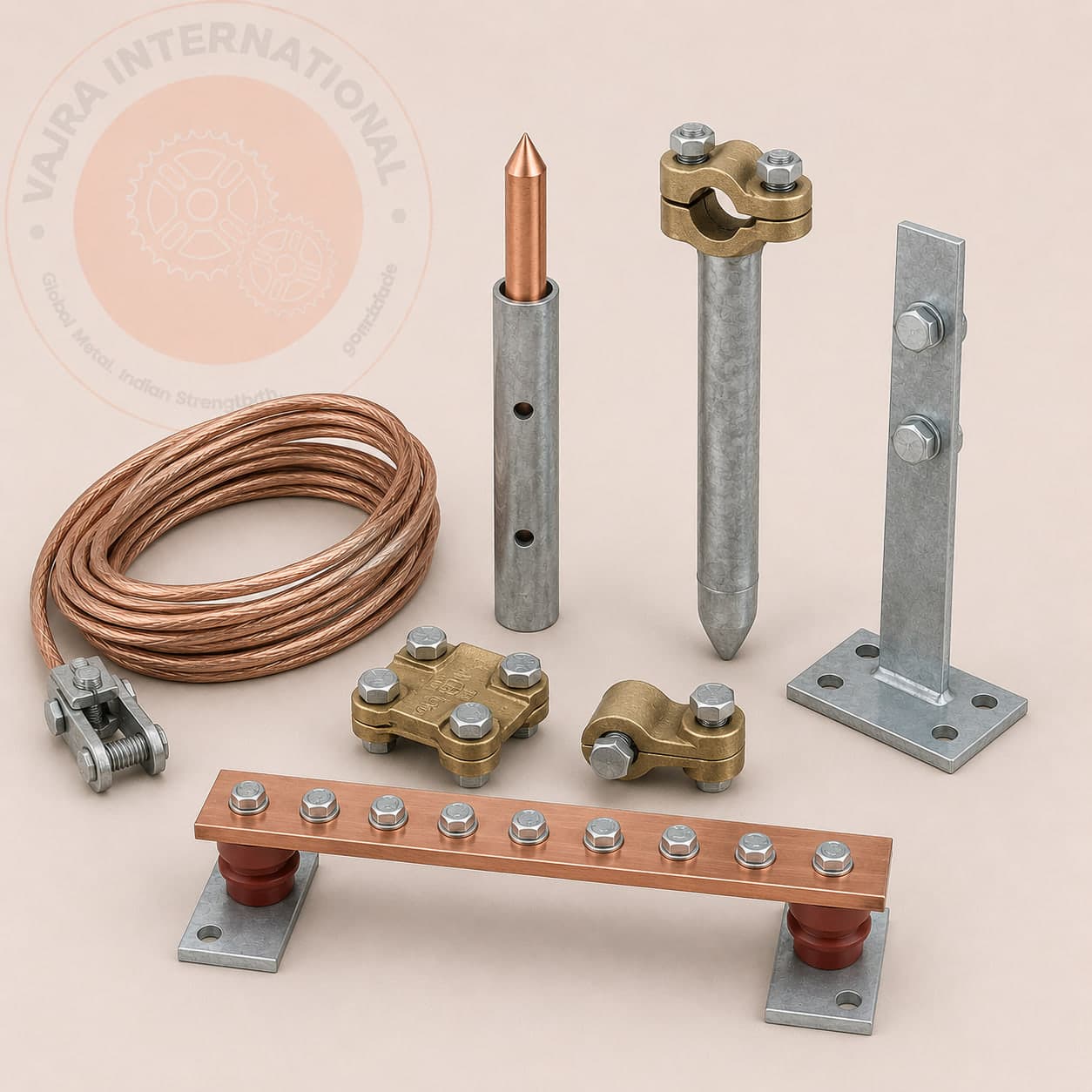
Earthing & Grounding Systems
Earthing plates, pipes, rods/electrodes, and copper/GI strips and wire for safe, low-impedance grounding of plant and buildings.
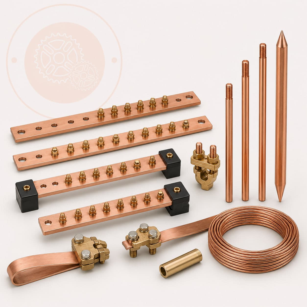
Lightning Protection
Air terminals, down conductors, and bonding hardware for structural lightning protection systems tied into the earthing grid.
Solar EPC case studies
Real export projects for this sector, with the standards and outcome specified.
Utility-Scale Solar Module Mounting Structures
Engineering and fabrication of ground-mounted solar structures, designed to withstand high wind loads and outdoor exposure.
Read case study Saudi Arabia · PowerSubstation Earthing & Lightning Protection Systems
Provision of copper-bonded ground rods and hot-dip galvanized grounding strips for electrical safety earthing. Engineered to meet strict soil resistivity requirements.
Read case study United Arab Emirates · Data CentreHDG Cable Trays for Gulf Infrastructure Projects
Supply of heavy-duty hot-dip galvanized cable trays and custom fittings to support critical power cabling. Designed and certified to IEC 61537 and ASTM A123.
Read case studyCommon questions
IEC 62305-3 defines four Lightning Protection Levels (LPL) based on the rolling sphere radius and collection efficiency required to intercept lightning strokes before they reach the protected structure. LPL I uses a 20 m rolling sphere (collection efficiency ≥98%) and is required for structures with the highest consequence of lightning strike: petrochemical facilities, explosive materials stores, critical data centres, and hospitals. LPL II uses a 30 m sphere (95% efficiency) and applies to large public buildings and industrial facilities with fire risk. LPL III uses a 45 m sphere (90%) for commercial warehouses and manufacturing facilities without explosive content. LPL IV uses a 60 m sphere (80%) for residential and low-risk structures. The practical implication: smaller rolling sphere radius = air terminals positioned closer together, more down conductors (one per 10 m perimeter for LPL I and II; one per 15 m for LPL III and IV), and deeper earth termination. Any structure with flammable, explosive or high-value content must be classified LPL I or II minimum, including rooftop inverter rooms on commercial buildings and substation control buildings. The LPL classification drives the entire material schedule: conductor sizing, earth electrode depth, and surge protection device rating.
No. ESE air terminals are not recognised by IEC 62305-3 as providing any extended zone of protection beyond a conventional Franklin rod. IEC 62305-3:2010 Annex A explicitly states that no enhanced or early streamer terminal type has demonstrated consistent, repeatable protection improvement under controlled test conditions. ESE terminals are recognised by NFC 17-102 (French standard) and UNE 21186 (Spanish standard), and are commercially common in GCC markets where the French standard is sometimes accepted by local authorities. However: if your project specification cites IEC 62305 as the design basis, which most EPC contracts in the Gulf, Australia, UK and Southeast Asia do, a lightning protection design built solely on ESE terminals will not pass technical review by an IEC-competent engineer. The risk: designing the system on ESE-claimed protection radii (typically 40–60 m claimed for LPL I ESE terminals vs 20 m for conventional) means the system is physically under-specified if ESE performance is not validated for your LPL. Specify conventional Franklin rods with rolling sphere positioning analysis unless the authority having jurisdiction explicitly permits NFC 17-102 or UNE 21186 as the design basis.
Solar farm earthing has three distinct design problems that differ from building earthing. First: DC string earthing. In a string inverter system the DC strings are floating relative to earth, neither positive nor negative terminal is intentionally earthed. The earthing design must provide a low-impedance fault return path from any string conductor to the inverter's ground fault detection circuit (GFDI), without intentionally grounding either DC terminal. Second: the earthing grid must cover a distributed area (often 20–100 hectares) without natural earth points, a continuous earthing grid of GI or copper flat strip must run along the cable management routes under the arrays, bonded to every mounting structure at ≤30 m intervals. Third: the inverter station and HV transformer require a Type B ring earth electrode per IEC 62305-3, with earth rods at corners, sized to the grid operator's specified earth resistance (typically <1 Ω for the substation, <10 Ω for the inverter station). IEC 62446-1 governs commissioning documentation. DC insulation resistance ≥1 MΩ per string and earth continuity between module frames and the main earthing terminal must be verified and recorded before grid connection.
GI earth pipes (IS 3043, 40 mm bore, 2.5 mm wall, HDG per IS 4736) are adequate for most standard applications: commercial and industrial building earthing, telecom towers, solar farm array earthing in inland sites, and power distribution substations in non-corrosive soil. The zinc coating life in standard Type C1/C2 soil (pH 6–8, moderate clay or loam, no chemical contamination) is typically 15–25 years, within the design life of most projects. Copper-bonded earth rods are the correct specification in three specific conditions: (1) Corrosive soil classified Type C3 or C4 per IS 3043 Annex D, pH below 5 or above 9, permanently waterlogged ground, high chloride or sulphate content, coastal sites within 1–2 km of the sea. In C3/C4 soil, zinc coating may be consumed in 5–10 years; copper corrodes at <0.002 mm/year and lasts the full project design life. (2) High fault current installations. HV substations where earth fault current exceeds 1,000 A require copper conductors per IS 3043 for adequate fault current capacity. (3) Earthing under permanent structures, if the electrode is buried under a concrete slab or road where excavation and replacement is impractical, the premium for copper over the full project life is far lower than the replacement cost. If your project specification simply says 'copper required' without citing the IS 3043 soil classification, ask the specifying engineer to confirm which condition applies. GI is frequently over-specified as a default.
Indian utility-scale solar mounting structures are designed to IS 875 Part 3 (wind loads) and IS 1893 Part 1 (seismic zones) as the primary structural codes, with material specified to IS 2062 Grade E250 (equivalent to S250 structural steel). The IS 16169:2014 standard specifically covers ground-mounted solar photovoltaic structures and recommends a minimum design life of 25 years with appropriate corrosion protection. Hot-dip galvanizing to IS 4759 / ASTM A123 is the standard finish for all below-ground and weather-exposed members. CEA (Central Electricity Authority) regulations also require that module mounting structures for utility projects above 1 MW be designed and certified by a structural engineer. For export projects: IEC 62817 provides the international guideline for solar tracker and fixed-tilt structure design, and is referenced by most Gulf and Southeast Asian EPCs in their project specifications.
Vajra manufactures fixed-tilt ground-mount structures for both portrait (1P) and landscape (2P) module orientations across standard tilt angles of 10°, 15°, 20°, 25° and 30°, custom tilt angles are available within the same lead time. Adjustable-tilt structures (seasonal adjustment at 2–3 positions during the year) are also available for sites where manual bi-annual adjustment is practical and the yield gain justifies the added cost. Pile-driven foundations (using galvanized MS piles or hollow-section steel ground screws) are the standard foundation type for most agricultural and sandy soils; ballasted structures are available for rooftop C&I applications. For each structure, we provide a structural calculation report confirming section sizes against the site's IS 875 Part 3 wind speed zone, along with shop drawings and a bill of materials. Container-load quantities are standard, most 5–20 MW utility project supply fits within 2–4 × 40HC containers per MWp of panels supported.
Procurement guides for solar epc
Sourcing Solar Mounting Structures from India: A Buyer's Guide
How to specify, price and import solar mounting structures from India, system types, galvanizing choices, wind and snow load inputs, the standards that apply, what to include in your BOQ, and the mistakes that delay commissioning.
Read guide Cornerstone Guide · 11 min readImporting Cable Trays from India: A Buyer's Guide
How to specify, price, certify and ship cable tray from India, written by a manufacturer. Types, finishes, the standards that matter, what drives cost, and the mistakes that cost importers money.
Read guide Cornerstone Guide · 10 min readSourcing Earthing & Grounding Systems from India: A Buyer's Guide
How to specify, price and import earthing electrodes, plates, rods and strip from India, electrode types, the IS 3043 / IEC 62561 standards, material choices, what documentation to require, and the mistakes that create hidden re-grounding costs.
Read guideEngineering resources for solar epc
India's Cable Tray Manufacturing Sector: A Buyer's Sourcing Guide
A structured look at India's cable tray manufacturing landscape, covering where the production clusters are, what certifications to demand, and how to evaluate a factory before placing an export order.
Read guide Export IntelligenceCable Tray Manufacturer in Kolkata and Howrah: Factory Direct Sourcing
A sourcing reference for project buyers looking at cable tray supply from Kolkata and Howrah. Covers the geography, what factories actually make here, and how to engage a West Bengal manufacturer directly for export orders.
Read guide Technical GuideLadder Cable Tray vs Perforated Cable Tray: Selection Guide
A side-by-side comparison of ladder and perforated cable tray covering load capacity, ventilation, cable type suitability, installation cost, and the IEC 61537 requirements that apply to each. Use this guide to confirm your selection before specifying to project drawings.
Read guideSupplying solar epc? Let's scope it.
Send drawings, a BOQ, or a simple description. You'll get a structured quotation covering specification, finish, lead time and Incoterms, from the manufacturer, not a middleman.
- MTC · COO · inspection reports
- ±0.01 mm precision · in-house QA
- FOB · CIF · CFR to all major ports