

Data Centres
Perforated and ladder cable trays, busbars and earthing for high-density data-centre power and network containment.
What this sector needs
Data-centre fit-outs need clean, high-capacity containment and solid earthing. Vajra supplies perforated and ladder trays, copper busbars, and earthing systems finish-matched for white-space and plant rooms.
Product lines for this sector
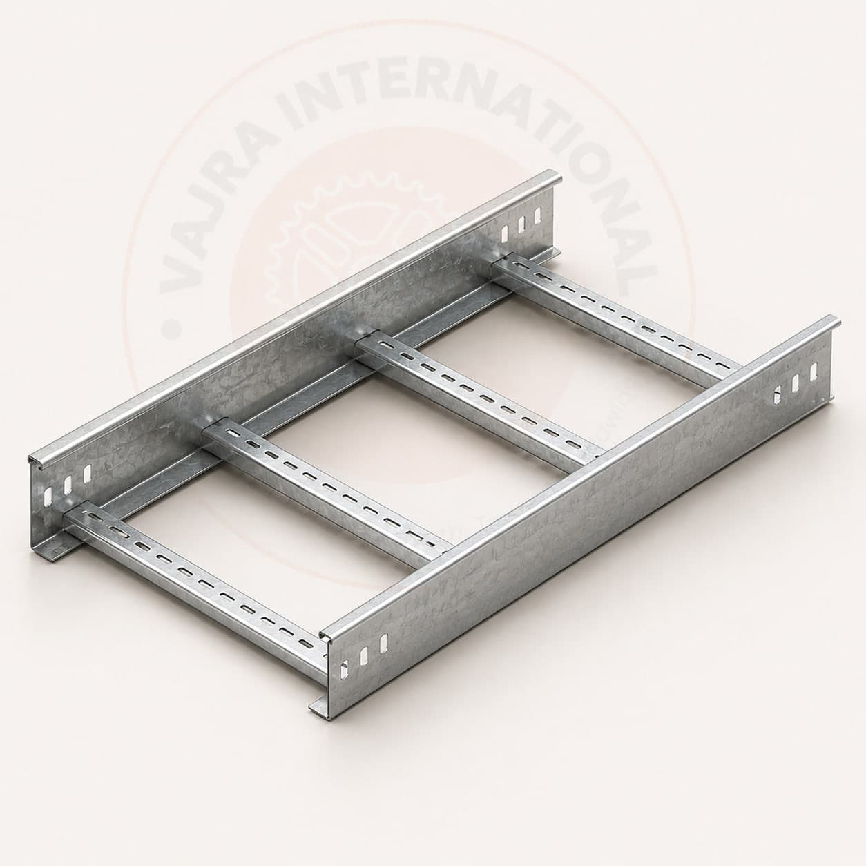
Cable Trays
Ladder, perforated, and raceway cable trays roll-formed in MS, GI, SS and aluminium, sized and finished to project load and environment.
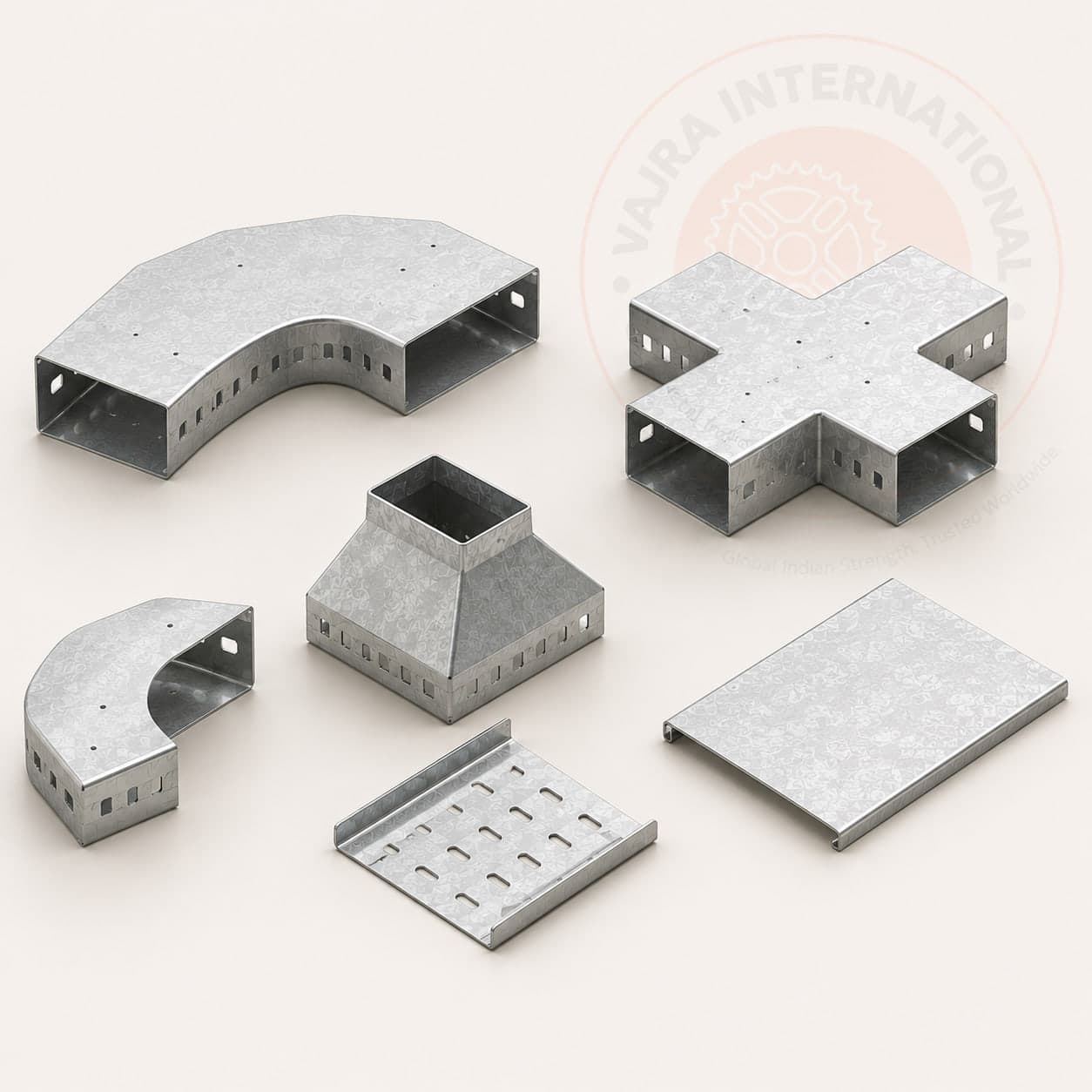
Cable Tray Accessories & Fittings
The complete fittings range, bends, tees, reducers, covers, couplers and supports, finish-matched to the tray system from one supplier.
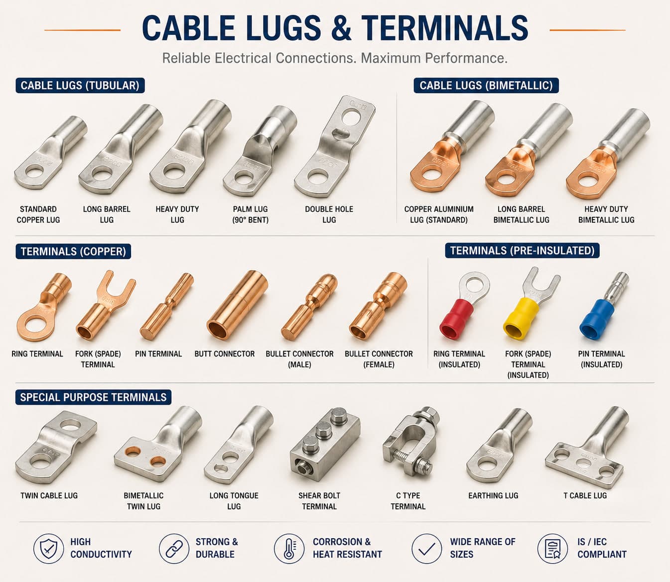
Copper Busbars & Strips
Electrolytic copper busbars and strips, cut, punched, bent and tinned to panel and switchgear drawings.
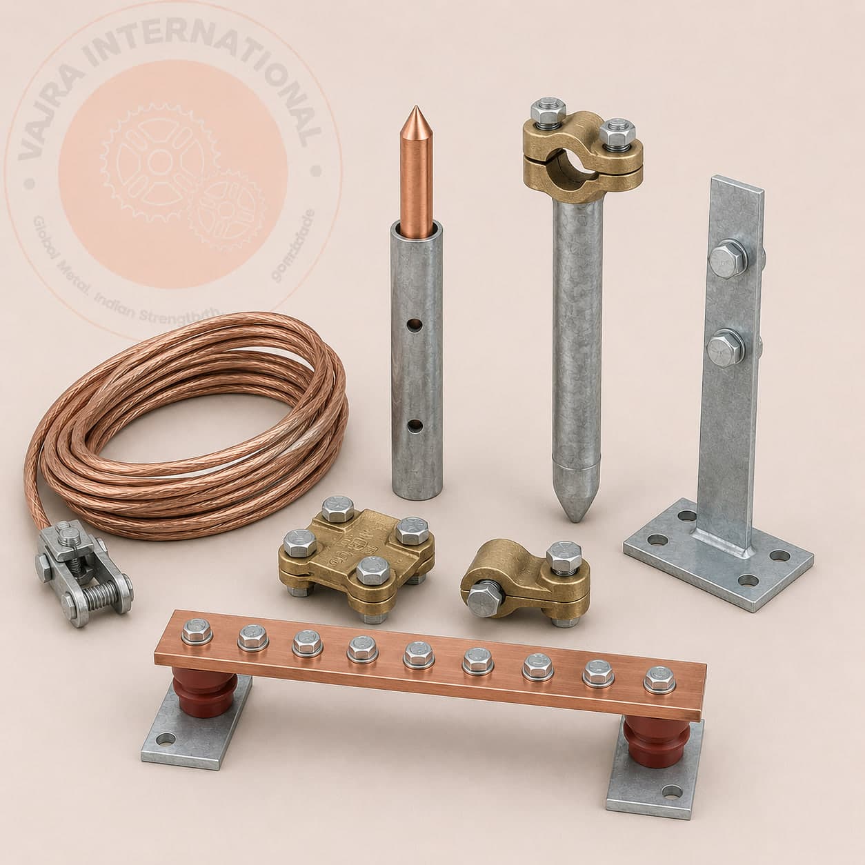
Earthing & Grounding Systems
Earthing plates, pipes, rods/electrodes, and copper/GI strips and wire for safe, low-impedance grounding of plant and buildings.
Data Centres case studies
Real export projects for this sector, with the standards and outcome specified.
Substation Earthing & Lightning Protection Systems
Provision of copper-bonded ground rods and hot-dip galvanized grounding strips for electrical safety earthing. Engineered to meet strict soil resistivity requirements.
Read case study United Arab Emirates · Data CentreHDG Cable Trays for Gulf Infrastructure Projects
Supply of heavy-duty hot-dip galvanized cable trays and custom fittings to support critical power cabling. Designed and certified to IEC 61537 and ASTM A123.
Read case studyCommon questions
IEC 61537:2006 (Cable Management Systems) defines the fill ratio as the ratio of total cable cross-sectional area installed in the tray to the tray's usable internal cross-section. The standard recommends a maximum fill ratio of 40% for ladder trays and 60% for perforated trays, the difference reflects heat dissipation: open ladder rungs allow greater airflow for power cables at full load rating. A 300 mm wide × 50 mm deep ladder tray has a usable internal cross-section of approximately 13,000 mm²; at 40% fill, the maximum total cable cross-section is 5,200 mm². Why this directly affects your order: over-filling a tray reduces cable current-carrying capacity. IEC 60364-5-52 Clause 7.3 applies thermal derating correction factors for grouped cables in filled trays, if fill ratio exceeds the design value, you must either derate the cable or specify a wider tray. Share your cable schedule (count and individual outer diameter) with your RFQ and our technical team returns a tray-width recommendation with fill ratio confirmation before you order.
TIA-942-B (the US data centre infrastructure standard) recommends a maximum 60% fill ratio for pathway capacity planning, this is the ratio of total cable cross-section to internal tray cross-section. IEC 60364-5-52, which governs data centres built to European and IEC standards (UAE, Australia, Singapore), recommends 40% fill for ladder trays carrying power cables and 60% for perforated trays carrying data and signal cabling. The practical difference matters: TIA-942 was written primarily for telecoms copper and fibre cabling, where thermal derating is not a concern. Applying TIA-942's 60% fill to a tray carrying 185 mm² power cables will under-derate the cable for its actual thermal load. For data centres: apply IEC 60364-5-52 to power trays (40% fill) and TIA-942 to data trays (60% fill). Always size power and data trays separately, combining them onto one fill ratio calculation is the most common sizing error in data centre cable management specifications.
IEC 62305-3 defines four Lightning Protection Levels (LPL) based on the rolling sphere radius and collection efficiency required to intercept lightning strokes before they reach the protected structure. LPL I uses a 20 m rolling sphere (collection efficiency ≥98%) and is required for structures with the highest consequence of lightning strike: petrochemical facilities, explosive materials stores, critical data centres, and hospitals. LPL II uses a 30 m sphere (95% efficiency) and applies to large public buildings and industrial facilities with fire risk. LPL III uses a 45 m sphere (90%) for commercial warehouses and manufacturing facilities without explosive content. LPL IV uses a 60 m sphere (80%) for residential and low-risk structures. The practical implication: smaller rolling sphere radius = air terminals positioned closer together, more down conductors (one per 10 m perimeter for LPL I and II; one per 15 m for LPL III and IV), and deeper earth termination. Any structure with flammable, explosive or high-value content must be classified LPL I or II minimum, including rooftop inverter rooms on commercial buildings and substation control buildings. The LPL classification drives the entire material schedule: conductor sizing, earth electrode depth, and surge protection device rating.
Start with the IEC 60439 free-air rating at 30°C: a 100×10 mm copper busbar is rated 960 A. At 45°C ambient, apply the de-rating factor of 0.91, giving 960 × 0.91 = 874 A, which is below 1,000 A. Step up to 120×10 mm, rated 1,150 A at 30°C: de-rated to 1,150 × 0.91 = 1,047 A at 45°C. That provides adequate margin. At 50°C (common in unair-conditioned switchrooms in Rajasthan and Gulf sites), the de-rating factor is 0.87, use 160×10 mm (1,500 A × 0.87 = 1,305 A) for a 1,000 A load at 50°C ambient. Always apply ambient de-rating: the IEC table value at 30°C is a catalogue number, not the real-world capacity at Indian or Middle Eastern ambient temperatures.
Ladder cable trays are the standard for data centre overhead routing for two reasons: airflow and weight. Ladder trays provide open bottom rungs that allow cable heat dissipation in high-density rows where IEC 60364-5-52 thermal derating would otherwise reduce current-carrying capacity if perforated trays were used. For data cabling (fibre, Cat 6A, 25GBase-T) running in separate containment from power, wire mesh tray (basket tray) is increasingly specified in hyperscale environments, it allows easy visual inspection of fibre runs and simplified access without cutting out sections of solid-bottom tray. Finish selection: hot-dip galvanized (HDG) for raised-floor plant rooms; powder-coated white or grey for white-space rows where aesthetics matter; stainless steel 316L for facilities requiring washdown compatibility (pharma, food-grade edge data centres). Vajra supplies ladder trays from 50 mm to 1,000 mm in widths, with depths from 50 to 150 mm, in HDG, pre-galvanized and stainless, with a full range of fittings (tees, crosses, reducers, inside/outside bends, splice plates).
IEC 60364-5-54 and TIA-607-C (the main data centre earthing and bonding standards) both require a dedicated Telecommunications Main Earthing Busbar (TMEB) as the equipotential reference for the IT and power distribution systems. The TMEB is typically a 50×6 mm or 63×6 mm electrolytic tough pitch (ETP) copper flat bar (IS 5082 / EN 13601), surface-tinned for contact resistance stability, mounted on insulators on the MDF room wall. From the TMEB, copper conductors of minimum 16 mm² bond all server rack earth rails, UPS earth bars, and the structural steel back to the building main earth terminal. For N+1 and Tier III/IV facilities, the earthing ring network also requires a separate lightning protection earth termination per IEC 62305-3. Vajra supplies ETP copper busbars in standard sections (25×3, 32×4, 50×6, 63×6, 80×8, 100×10 mm) with drilling and tinning to order.
Procurement guides for data centres
Sourcing Copper Busbars from India: A Buyer's Guide
How to specify, size and import ETP copper busbars from India, grades, tempers, tinning, the standards that matter, what drives cost, documentation requirements, and the mistakes that inflate procurement cost.
Read guide Cornerstone Guide · 11 min readImporting Cable Trays from India: A Buyer's Guide
How to specify, price, certify and ship cable tray from India, written by a manufacturer. Types, finishes, the standards that matter, what drives cost, and the mistakes that cost importers money.
Read guide Cornerstone Guide · 10 min readSourcing Earthing & Grounding Systems from India: A Buyer's Guide
How to specify, price and import earthing electrodes, plates, rods and strip from India, electrode types, the IS 3043 / IEC 62561 standards, material choices, what documentation to require, and the mistakes that create hidden re-grounding costs.
Read guideEngineering resources for data centres
India's Cable Tray Manufacturing Sector: A Buyer's Sourcing Guide
A structured look at India's cable tray manufacturing landscape, covering where the production clusters are, what certifications to demand, and how to evaluate a factory before placing an export order.
Read guide Export IntelligenceCable Tray Manufacturer in Kolkata and Howrah: Factory Direct Sourcing
A sourcing reference for project buyers looking at cable tray supply from Kolkata and Howrah. Covers the geography, what factories actually make here, and how to engage a West Bengal manufacturer directly for export orders.
Read guide Technical GuideLadder Cable Tray vs Perforated Cable Tray: Selection Guide
A side-by-side comparison of ladder and perforated cable tray covering load capacity, ventilation, cable type suitability, installation cost, and the IEC 61537 requirements that apply to each. Use this guide to confirm your selection before specifying to project drawings.
Read guideSupplying data centres? Let's scope it.
Send drawings, a BOQ, or a simple description. You'll get a structured quotation covering specification, finish, lead time and Incoterms, from the manufacturer, not a middleman.
- MTC · COO · inspection reports
- ±0.01 mm precision · in-house QA
- FOB · CIF · CFR to all major ports