

Skip to content
Technical Guide

Maintenance-Free Earthing Electrodes and Backfill Compound: What Actually Lowers Resistance

Salt and charcoal give you a great reading on commissioning day and a creeping failure two monsoons later. What really holds a low earth resistance over years, and what just looks good at handover.

Vajra International Engineering · Applications & Specification Team 6 min
Maintenance-Free Earthing Electrodes and Backfill Compound: What Actually Lowers Resistance — Vajra International, cable tray, earthing & steel manufacturer and exporter, Howrah, India
Maintenance-Free Earthing Electrodes and Backfill Compound: What Actually Lowers Resistance — technical guidance from Vajra International, ISO 9001:2015 certified cable tray, earthing & steel manufacturer and exporter, Howrah, India.

Pour a bag of salt and charcoal around an earth pit and the resistance reading drops nicely on commissioning day. Come back after two monsoons and it has crept up again, the salt has leached away, and the electrode is corroding faster than before it was treated. We still see this on sites across India, written into method statements that are decades old. The maintenance-free electrode and the right backfill compound exist precisely because the old salt-and-charcoal recipe does not last. Here is what actually holds a low earth resistance over years, and what just looks good on the test report at handover.

What 'maintenance-free' actually means

A maintenance-free earthing electrode is usually a pipe-in-pipe design. There is an outer pipe, galvanized steel for budget work or copper-bonded steel for longer life, with an inner conductor, and the gap between them is packed with a conductive crystalline compound. The pipe is perforated near the bottom. The compound draws moisture from the surrounding soil and pushes current out into a far larger volume of earth than the bare metal surface could reach on its own. Maintenance-free means you are not meant to pour water or recharge salt down it every season. It does not mean fit and forget for ever, because you still test it. But a properly installed unit with the correct backfill holds its reading for years rather than months.

Why salt and charcoal is the wrong fix

Common salt lowers resistance by making the soil water more conductive, but it does three things you do not want. It washes away with groundwater, so the effect fades. It is corrosive, so it attacks the very electrode it surrounds, galvanized steel most of all. And it is seasonal, dropping out almost completely as the soil dries. Charcoal holds a little moisture but is inconsistent and breaks down over time. The reading you take the morning after backfilling with salt is the best that pit will ever give. Every reading after that is worse. That is the exact opposite of what an earthing system is supposed to do, which is stay reliable when you need it.

Backfill compounds, and which does what

  • Bentonite: a natural clay that swells and holds moisture well, useful in dry or sandy soil. It lowers contact resistance but is not very conductive on its own, and it can crack if it dries out completely.
  • Conductive carbon backfill (Marconite and similar aggregates): stays conductive whether wet or dry, used where the soil is rocky or resistivity is very high. It costs more but is very stable over time.
  • Crystalline conductive compound, the type packed inside maintenance-free electrodes: hygroscopic, so it draws moisture in and keeps conducting, and it is meant to recharge naturally from soil and rain.
  • Ground enhancement material (GEM): a cement-like conductive backfill that sets in place, used around rods and in trenches for earth grids that must not shift.

The number you are chasing, and how soil fights you

IS 3043 expects an earth resistance low enough for the protective device to operate and for touch and step voltages to stay safe. In practice that means roughly 1 ohm for large stations, around 5 ohm for many industrial installations, and up to about 10 ohm where the standard permits for smaller systems. The enemy is soil resistivity, which runs from under 50 ohm-metre in damp clay to several thousand in dry rock or sand. No compound beats physics. In very high-resistivity ground you reach the target by adding electrodes in parallel, by going deeper to a moist layer, or both, with the right backfill multiplying the effect of each electrode. One electrode plus a miracle powder is not a design. The layout is the design.

Getting the install right so the reading holds

The compound only works in full contact with both the electrode and the surrounding soil, with no air gaps. Mix and place it the way the maker states, in a bore wide enough to leave a proper annulus around the electrode, and water it in so it beds down. Bring the conductor to the electrode with a bolted or exothermic-welded joint that is itself protected, because a corroded joint at the top of a perfect electrode still wrecks the system. Fit a test link in an inspection chamber at each pit so the reading can be taken at the electrode rather than through the whole network. Then test by the fall-of-potential method in the dry season, when the soil is at its worst, and write the figure down.

The honest earth resistance is the one you measure at the end of the dry season, not the morning after you poured salt into the pit. Design for the dry reading and the wet months look after themselves.

Specifying earthing for a substation, plant or tower farm in difficult soil? We manufacture copper-bonded and GI maintenance-free electrodes, earth plates and conductive backfill, and supply soil-resistivity-based sizing with MTC and a NABL test report.

Request an earthing quote

About the author

Vajra International Engineering

Applications & Specification Team

Our applications engineering team draws on 50+ years of combined manufacturing experience across industrial cable management, earthing systems, structural steel and precision metal components. We write from the factory floor — from specifying raw material grades through to shipping documentation.

  • ISO 9001:2015 certified manufacturing
  • EEPC / RCMC registered exporter
  • Suppliers to Defence, Railways and Energy sectors

Spec these products

The products covered in this article — ready to quote.

Frequently asked questions

Specification, compliance and procurement questions our engineering team answers most often.

Which standard governs earthing plate design and installation in India and abroad?
IS 3043 is the Indian code of practice — it defines plate material, minimum dimensions (600×600 mm copper or GI), depth of burial, backfill, watering arrangement and the resistance acceptance target. IEC 62561-2 covers the same component requirements internationally, and BS 7430 is the British equivalent still widely cited in African and GCC project specifications. Our plates are manufactured to IS 3043 with material certificates written to align with IEC 62561-2, so the same shipment satisfies an Indian utility tender and an international EPC's BOQ without re-testing.
What does IS 3043 specify for pipe electrodes — bore, wall thickness and burial depth?
IS 3043 clause 4.3 covers pipe electrodes. The minimum bore is 38 mm (1.5 inch NB) with a 4–5 mm wall thickness; 50 mm NB is the more common site choice for better soil contact surface. Standard burial depths are 2.5 m or 3.0 m, but IS 3043 recommends going deeper when soil resistivity is above 50 Ω·m — depth reduces resistance far more effectively than wider bore. An inner perforated pipe (25 mm NB) carries the backfill and watering column. Our standard electrode is 50 mm NB outer, 25 mm NB inner, 3.0 m length, HDG inside and out.
What does IEC 62561-2 Class H require for copper-bonded earth rods, and how do you verify compliance?
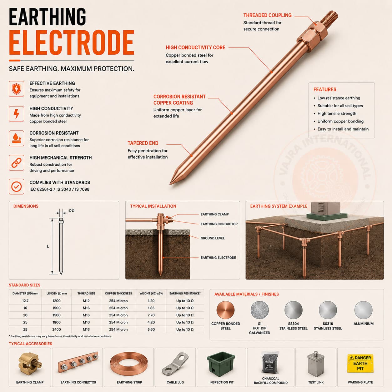
IEC 62561-2 Class H sets a minimum copper coating thickness of 250 µm on the rod's outer surface. Verification uses either the Faraday-cup electrochemical stripping method or a cross-section SEM measurement — both are described in IEC 62561-2 Annex A. We test a sample from every production batch and include the thickness certificate in the dispatch document pack. A rod that does not meet 250 µm Class H cannot be described as IEC 62561-compliant, regardless of the supplier's claim — ask for the test method and measurement record, not just a certificate.
What strip sizes does IS 3043 specify for industrial earth grids and substation earthing?
IS 3043 clause 5.4 covers conductor sizing. For general industrial earthing grids, 25×3 mm GI strip is the working minimum. Substations, distribution transformers and data centre main earth bars step up to 50×6 mm GI strip or 50×3 mm tinned copper, sized to carry the maximum earth-fault current for the fault-clearing time set by the protective relay. The cross-section formula is from IEEE 80 (or IS 3043 Annex B) — we size on request when you share the prospective fault current and relay setting.
Which materials do you work with?
Mild steel, structural steel (IS 2062), stainless steel (304/316), aluminium, electrolytic copper and brass — selected and certified to application.
Which standards do you build to?
Standards-based engineering across ASTM, IEC, EN, DIN, NEMA, BS and IS — including IS 4759 / ASTM A123 galvanizing, IS 2713 gratings, and IEC 61537 / IS 12352 cable management.
Request a Quotation

Put a spec in front of the people who make it.

Send drawings, a BOQ, or a simple description. You'll get a structured quotation covering specification, finish, lead time and Incoterms — from the manufacturer, not a middleman.

  • MTC · COO · inspection reports
  • ±0.01 mm precision · in-house QA
  • FOB · CIF · CFR to all major ports

Trade updates, new product lines, export schedules.

One email when it matters. No marketing noise.

Unsubscribe any time · No spam · Vajra International Exports