
Earthing system investigations by electrical safety bodies consistently show the same pattern: 73% of failures are connection failures, not electrode failures. The rod did not fail. The plate did not fail. The joint between the conductor and the electrode corroded until it went open-circuit, and the system lost its protective function entirely, often years before anyone noticed. Engineers spend months specifying the right electrode for the soil resistivity and forget that the joint is the weakest link in the chain. This guide covers both: electrode selection for the soil, and the connection method that keeps the system intact for 30 years.
Understanding soil resistivity first, the number that drives every other decision
Soil resistivity (ρ, measured in Ω·m) determines how much of the electrode system you need. Sandy coastal soil: 5–50 Ω·m. Clay: 20–100 Ω·m. Rocky ground: 1,000–10,000+ Ω·m. The same copper-bonded rod that achieves 5Ω in Kolkata clay may only achieve 120Ω in Rajasthan rocky soil. IEEE 80 / IS 3043 both require you to measure soil resistivity with a Wenner array before specifying the electrode configuration, not after installation. If your earthing contractor has never mentioned soil resistivity measurement, find a different contractor.
Earth plates, maximum contact area in a fixed location
GI earth plates (600×600×6 mm standard per IS 3043, copper 600×600×3.15 mm) are buried horizontally at 2–3 m depth in maintained earth pits. Their advantage is large contact surface area, a single 600×600 mm plate gives 0.72 m² of soil contact. Their limitation is that contact area is fixed; you cannot extend the plate depth if soil resistivity improves at depth. They require access for periodic inspection and water treatment in dry zones. We supply GI plates (IS 2062 Gr. A, minimum 6 mm thickness) and copper plates (IS 613 / ASTM B152 electrolytic copper) with matching funnel assembly, backfill charcoal and salt treatment kit as a complete pit package.
GI pipe electrodes, the workhorse of IS 3043 practice
Hot-dip galvanized mild-steel pipe electrodes (40 mm NB minimum, 50 mm NB preferred) driven to 2.5–3 m depth with perforated lower section are the most-specified earthing electrode in Indian substation and telecom tower practice. Their advantage is that they can be extended by coupling additional pipe lengths if initial resistance measurement is too high. Pipe electrodes are driven, not drilled. GI pipe has adequate wall thickness to survive driving through soft and medium soil with a drive cap. The pipe wall must be minimum 3 mm (IS 1239 medium duty) to avoid collapsing under impact.
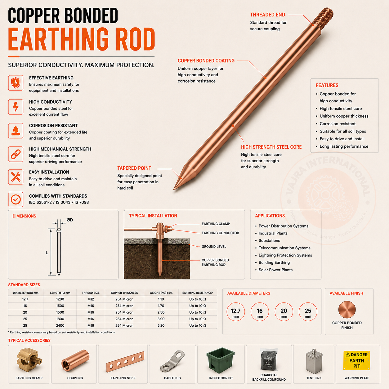
Copper-bonded rods, the export specification for most international projects
Copper-bonded steel-core rods (14.2 mm and 17.2 mm diameter standard, 1.5 m and 3 m lengths) electrolytically coated with 99.9% copper to 0.25 mm minimum thickness are the dominant electrode type for GCC, European and Australian projects. The steel core provides driving strength; the copper bond provides corrosion resistance and low contact resistance in the soil-metal interface. Multiple rods can be coupled and driven to 6–9 m depth to reach lower-resistivity soil layers. IEEE 80 Annex B gives the design equations. For a 50 kVA substation in GCC soil (ρ ≈ 200 Ω·m), you typically need 4–6 rods at 6 m depth in a 3 m grid pattern to achieve under 5Ω body resistance. We supply 14.2 mm and 17.2 mm bonded rods in 1.5 m sections with thread-and-coupler for deep driving.
Conductors and, crucially, the joints
GI flat strip (25×3, 25×6, 40×5 mm standard) and copper strip (25×3, 32×6 mm) form the horizontal earth grid and equipment bonding network. Always match the conductor material to the electrode material: copper conductors to copper electrodes; GI conductors to GI or copper-bonded electrodes (mild steel core is compatible). Mixed joints, copper conductor clamped to GI pipe, create a galvanic cell. Zinc anode, copper cathode. The zinc corrodes preferentially. Joint fails in 8–12 years outdoors, faster in coastal or acidic soil. For permanent joints, exothermic welding (Cadweld/Thermoweld process) creates a molecular-level copper weld that is the only IS 3043 / IEEE 80 recommended method for substation and critical infrastructure earth connections. It cannot loosen, cannot corrode, and does not rely on bolt torque.
Specify the earth electrode for the soil, specify the conductor for the fault current, and specify exothermic welding for every permanent joint. Everything else is maintenance cost.
We supply copper-bonded earthing rods, GI pipe electrodes, earth plates, flat strip conductors and exothermic welding kits, with MTC and COO for international projects.