Specification, compliance and procurement questions our engineering team answers most often.
- How does UL 467 differ from IEC 62561-2, and which standard applies to US and Gulf projects?
- UL 467 (Grounding and Bonding Equipment) is the North American benchmark. It specifies a minimum copper coating of 10 mils (254 µm) on earth rods, almost identical to IEC 62561-2 Class H in practice. The test methods differ slightly, but rods produced to IEC 62561-2 Class H pass the UL 467 dimensional requirement. For US data centre or oil-and-gas projects importing from India, buyers typically ask for IEC 62561-2 certification and accept it in lieu of a formal UL listing. For GCC projects, IEC 62561-2 is the explicit standard in Saudi SEC and UAE DEWA earthing specifications.
- What does IS 3043 say about driven rod electrodes versus excavated plate or pipe electrodes?
- IS 3043 clause 4.4 covers rod electrodes. It specifies that rods must be metallic, driven vertically, with a minimum cross-section sufficient to carry the prospective fault current without overheating, and the top of the rod must be accessible in an inspection chamber. IS 3043 does not set a minimum copper coating for copper-bonded rods, it defers to the material standard. For driven rods specifically, IS 3043 prefers harder ground conditions where plates are impractical. In practice, copper-bonded rods are now the default for driven earthing in India because they combine the driving strength of steel with copper's corrosion resistance.
- Is there a galvanizing or coating requirement for buried earth strip under IS 3043?
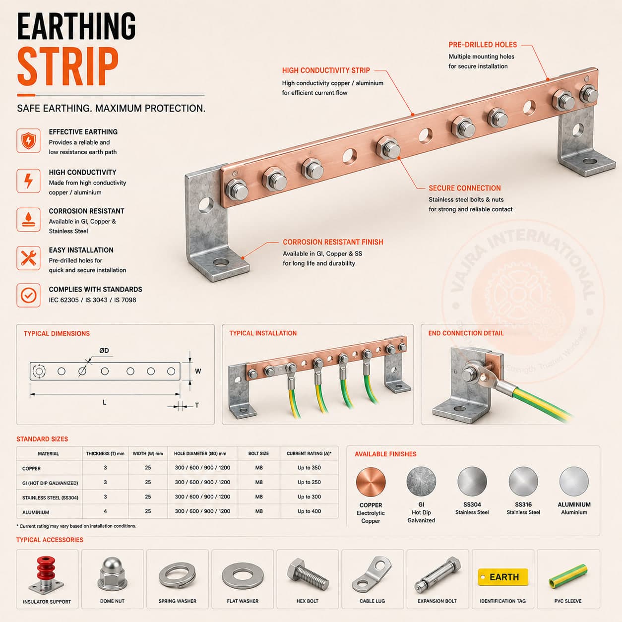
- IS 3043 requires GI strip used as a buried earth conductor to be hot-dip galvanized to IS 4759 (minimum 610 g/m² or 85 µm coating weight). Bare mild steel strip degrades rapidly in soil and is not acceptable. Our GI strip is drawn from IS 2062 E250 base material, hot-dip galvanized, and batch-certified to IS 4759 with thickness readings at three points per coil. Copper strip and tinned copper strip are used without a coating requirement, the base material is the corrosion protection.
- What do IS 3043 and IEC 62561 require for joints in buried earth conductors?
- IS 3043 clause 5.5 and IEC 62561-1 (clamps) both cover jointing. A bolted joint using stainless or galvanized hardware with a bimetallic washer is the minimum code-compliant method for accessible joints inside chambers. For buried joints, exothermic welding (Cadweld, Thermoweld or equivalent) creates a molecular-fusion connection that does not loosen, corrode or develop contact resistance over time, it is the gold standard for buried earth grid connections and is required by many utility and petrochemical specifications. We supply both jointing methods and the exothermic moulds, positioned for the strip size and joint angle.
- What are Bangalore data centres, Hyderabad pharma plants and Chennai port projects each specifying for plate earthing right now?
- We supply three distinct configurations to these clusters. Bangalore and Hyderabad data centres (CtrlS, NxtGen, Yotta, GPX) specify copper plates with bentonite GEM backfill and a per-pit acceptance target of ≤1 Ω, because the rack signal-reference grid demands it and the IS 1646 fire-safety earth requirement layers on top. Hyderabad pharma plants (Divi's, Dr Reddy's, Aurobindo) use IS 3043 GI plates for non-process earthing but copper plates in API manufacturing areas where GMP audit requires documented corrosion resistance. Chennai port and refinery expansions (IOCL, Coromandel) prefer copper-bonded rod arrays over plates for deep-strata low-resistivity access, but still use 600×600 copper plates at transformer body and neutral points. We stock all three configurations and ship within two to three weeks of order.
- Which export geographies are procuring Indian earthing plates at the highest volumes, and what documentation do they require?
- Saudi Arabia and UAE are our largest copper plate export markets, specifically for Vision 2030 industrial city projects (NEOM, Ras Al-Khair, KAEC), DEWA substation expansions and Aramco gas plant refurbishments. Each shipment requires an IEC 62561-2 material test certificate, a Saudi SASO conformity declaration or UAE ESMA self-declaration, and an Arabic-language installation guide. Kenya and Ethiopia are the next-largest, driven by Chinese-funded industrial park construction where Indian suppliers are specified by the local site engineers. Nigeria and Ghana round out the West African demand. All these markets require a certificate of origin from an approved Indian export chamber, we handle the full document pack.
- What is the IS 3043 resistance acceptance target for a pipe electrode installation, and how is it measured?
- IS 3043 targets less than 1 Ω for the completed earthing system measured at the terminal. For pipe electrodes, a single 3 m electrode in average Indian soil (resistivity 50–100 Ω·m) typically delivers 3–8 Ω, so two to four electrodes in parallel are needed to reach the system target. Measurement uses the three-electrode fall-of-potential method (Megger DET4TC2 or equivalent) at least 7 days after backfill compaction and during the dry season. We include the test procedure sheet and acceptance form in every pit kit.
- What makes a cable tray suitable for Zone 1 classified areas, does it need ATEX certification?
- Cable trays are passive components and are not classified as electrical equipment under IEC 60079, they do not carry ATEX or IECEx certification marks. Compliance in Zone 1 and Zone 2 classified areas is achieved through the installation method, not through certification of the tray itself. What the standard (IEC 60079-14 Cl. 9.3.4) requires: all metallic cable management in a classified area must be electrically continuous and bonded to the facility earthing system, to prevent static charge accumulation that could create an ignition source. In practice this means: (1) A 4 mm² minimum copper bonding conductor must run across every tray joint coupler, bolt connections through coupler plates alone are not sufficient. (2) The tray run must be connected to the main earthing system at both ends, with intermediate bonds at ≤30 m intervals for runs exceeding 30 m. (3) Hot-dip galvanized mild steel or fibreglass (GRP) are the accepted tray materials in most Gulf and international classified area specifications. ARAMCO SAES-P-104 adds specific fill ratio and support spacing requirements beyond IEC.
- What does ARAMCO SAES-P-104 require for cable tray material, fill ratio, and documentation?
- Saudi Aramco Engineering Standard SAES-P-104 (Design and Installation of Cable Management Systems) specifies: material, hot-dip galvanized mild steel (for power and earthing runs) or fibreglass GRP (for instrumentation in classified areas); maximum fill ratio, 50% (more conservative than IEC 61537's 40% for ladder trays); support spacing, maximum 1,500 mm between bracket centres for horizontal runs, 900 mm for vertical runs; bonding, stainless steel bonding links across every tray joint, not clip-type spring connectors. Documentation required for ARAMCO project submissions: EN 10204 Type 3.1 MTC for the tray steel, HDG coating inspection report per ASTM A123 with actual XRF measurement values, dimensional inspection report confirming sheet thickness and rung pitch, and an engineering data sheet in ARAMCO-compatible format. Note: for named ARAMCO projects, suppliers must typically obtain project-specific approval against SAES-A-004 (Approved Vendor List), this is a pre-qualification process, not a standing product approval. We have prepared SAES-P-104 compliant document packages for EPC contractors on multiple ARAMCO project submissions.
- What is the difference between LPL I, II, III and IV in IEC 62305-3 lightning protection design?
- IEC 62305-3 defines four Lightning Protection Levels (LPL) based on the rolling sphere radius and collection efficiency required to intercept lightning strokes before they reach the protected structure. LPL I uses a 20 m rolling sphere (collection efficiency ≥98%) and is required for structures with the highest consequence of lightning strike: petrochemical facilities, explosive materials stores, critical data centres, and hospitals. LPL II uses a 30 m sphere (95% efficiency) and applies to large public buildings and industrial facilities with fire risk. LPL III uses a 45 m sphere (90%) for commercial warehouses and manufacturing facilities without explosive content. LPL IV uses a 60 m sphere (80%) for residential and low-risk structures. The practical implication: smaller rolling sphere radius = air terminals positioned closer together, more down conductors (one per 10 m perimeter for LPL I and II; one per 15 m for LPL III and IV), and deeper earth termination. Any structure with flammable, explosive or high-value content must be classified LPL I or II minimum, including rooftop inverter rooms on commercial buildings and substation control buildings. The LPL classification drives the entire material schedule: conductor sizing, earth electrode depth, and surge protection device rating.