

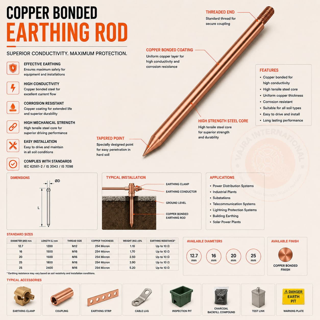
An electrical engineer at a data centre project in Chennai rang us after getting a persistently high earth resistance reading: 18 ohms instead of the specified 1 ohm. The rods had been in the ground for five years, the soil resistivity looked acceptable on paper, and the maintenance team had added more rods without improvement. When we visited the site, we found the copper bonded rods had lost their copper layer at the junction between the rod body and the threaded coupling. The soil in that part of Chennai is acidic (pH 4.5 to 5.0) and has elevated sulphate content from proximity to industrial effluent drainage. In acidic, sulphate-rich soil, even small imperfections in the copper bond become entry points for galvanic attack. Once the steel core is exposed at the interface, it corrodes fast and the rod loses electrical continuity.
The engineer had specified copper bonded rods because they appeared in his company's standard specification and cost less than solid copper. He had not specified a soil analysis, not checked the pH, and not reviewed the soil chemistry report. This is the most common earthing rod specification mistake we encounter.
How the three types are made
- Copper bonded (copper-clad steel): a carbon steel core with an electrolytically deposited copper layer. Standard coating is 250 µm of 99.9% pure copper per IEEE 837 or BS EN 50164-2. Some manufacturers offer 450 µm or 600 µm for aggressive soil conditions. The bond is metallurgical at the steel surface, not mechanical plating after the fact. The steel provides tensile strength for driving; the copper provides conductivity and corrosion resistance. Typically 60 to 70% cheaper than solid copper.
- Solid copper: pure copper (electrolytic tough pitch or deoxidised grade) from top to bottom. No bimetallic interface, no galvanic cell risk. More expensive, softer (bends in hard ground without a driving head), and heavier. The right choice in corrosive soils where even thick copper bonded coatings would fail, and in installations where ground movement could cause micro-cracking at a bonded interface over time.
- Galvanized iron (GI): carbon steel rod, hot-dip galvanized. The lowest-cost option. Zinc provides some corrosion protection, but dissolves in both acidic and strongly alkaline soils faster than copper. IS 3043 permits GI rods for temporary and low-risk installations. Not appropriate for permanent installations in industrial sites, data centres, substations, or any location where IS 3043 specifies a resistance target below 5 ohms.
What IS 3043 says about rod selection
IS 3043:2018 does not mandate copper bonded over solid copper. It specifies the required earth resistance for each type of installation: 1 ohm for generating stations, 2 ohms for major substations, 10 ohms for domestic installations. Section 9.3 states that electrode materials must be appropriate for the soil conditions and that GI rods are not suitable for permanent installations in acidic or corrosive soils. IEC 62561-2 (the international standard for earth electrodes) provides similar guidance.
The designer's job is to choose based on soil chemistry, target resistance, and design life. If no soil analysis has been done, the material selection is a guess.
Performance by soil type
- Neutral soil (pH 6.5 to 8.0), low chloride, low sulphate, resistivity above 100 ohm-m: copper bonded rods at 250 µm coating are fine. The electrochemical environment is mild, the copper layer lasts 20 to 30 years, and the cost saving over solid copper is worthwhile.
- Acidic soil (pH below 6.0): copper bonded with 450+ µm coating, or solid copper. Acidic conditions accelerate attack at the steel-copper interface wherever the bond has any imperfection. Solid copper eliminates the interface risk entirely.
- Alkaline soil (pH above 9.0): both copper bonded and solid copper perform well. GI rods are more susceptible in strongly alkaline conditions (zinc forms soluble zincate ions at high pH.
- High chloride soil (saline, coastal sites, industrial brine areas): solid copper, or copper bonded at 600 µm coating minimum. Chloride ions attack the passive film on copper at joints and couplings where oxygen depletion and crevice geometry combine.
- High sulphate soil (near industrial effluent, some black cotton soils): solid copper is preferable. Sulphate-reducing bacteria in sulphate-rich soil create a micro-environment that corrodes the bonded interface faster than bulk copper in the same conditions.
- Made ground or variable fill (construction debris, unknown chemistry): run a soil resistivity survey using the Wenner 4-pin method before specifying any rod type. Made ground resistivity varies enormously and standard 1.5 m rod length may be completely inadequate to reach low-resistivity strata.
Coupling design: the weak point in sectional rods
A 1.5 m rod is the minimum specified in IS 3043. Most data centres and substations use 3 m rods in two 1.5 m sections joined with threaded couplings. The coupling is the most vulnerable point in a copper bonded installation. Soil movement, poor thread engagement, or the wrong coupling material can break continuity at the joint even when the rod bodies themselves are intact.
The coupling must be stainless steel or solid copper, not carbon steel. Some suppliers ship mild steel couplings with copper bonded rods as a cost saving. This creates a bimetallic junction with a large area ratio) small coupling, large rod (exactly the geometry for accelerated galvanic corrosion. Solid copper rods below 3 m can be supplied as a single piece, eliminating the coupling concern for shorter installations.
Cost comparison over the full design life
Copper bonded rods at 250 µm coating cost roughly 30 to 40% of equivalent solid copper by weight. But if the soil is aggressive and the rod fails at year seven in a 30-year design-life installation, the replacement and remobilisation cost) excavation, new rods, re-testing, production downtime (makes the cheaper rod the more expensive choice over the asset life. A practical rule: if the soil analysis shows any of the aggressive conditions listed above, the additional cost of solid copper rods is recovered in the first avoided replacement cycle.
We have replaced GI earth rods that had corroded to breaking point inside three years. We have also pulled solid copper rods out of the ground after twenty years that looked almost new. The soil chemistry is the variable. The rod type is the decision you make based on it.
Vajra International manufactures copper bonded earthing rods, solid copper rods, GI earth electrodes and flat earthing strips at Howrah. All products supplied with IS 3043 and IEC 62561-2 test reports and material traceability documentation.