

A steel cable tray is a long metal conductor running right alongside the cables it carries, so it can double as an earth path, a parallel earth conductor, carrying fault current back and holding the whole run at one potential. It is a genuinely useful feature and it is more or less free, because the tray is already there. But it only works if the tray is electrically continuous from end to end and bonded back to the earthing system. Leave the continuity to chance and you get a tray that looks earthed, tests earthed on handover day, and quietly goes open-circuit at the first corroded joint. An earth path you cannot rely on is worse than none, because people trust it.
What 'parallel earth conductor' actually asks of the tray
For a tray to serve as a parallel earth conductor it has to do two things. It must carry the prospective fault current for the clearing time without overheating, which is a question of the tray's metal cross-section, and it must stay continuous across every joint and fitting along its length. The first is usually easy, because a steel tray has plenty of metal in it. The second is where it falls down, because a cable tray is not one piece of metal. It is dozens of sections bolted together, and each bolted joint is a contact that can loosen, paint over, or corrode until it stops conducting.
Why the joints break the earth path
A coupler that is mechanically strong is not automatically electrically good. Three things quietly break continuity at a joint. Paint or powder coating between the mating faces insulates the contact, so a painted tray bolted to a painted splice plate can carry almost no current across the joint. Corrosion grows an oxide film over the years that does the same thing. And a bolt that backs off under vibration loses the contact pressure the joint depended on. The run can look perfect and still be a string of isolated sections as far as fault current is concerned. That is why continuity must never be assumed just because the sections are bolted together.
Bonding jumpers, the cheap insurance
The fix is a bonding jumper across each joint, a short length of earthing conductor or a proprietary bonding strap bolted from one tray section to the next, bypassing the coupler so continuity does not rely on the bolted faces. On a galvanized tray with clean, tight, unpainted joints the coupler itself may be enough, but on painted trays, at expansion joints, and anywhere the run is the designated earth path, fit jumpers. At expansion joints they must be flexible so they do not snap as the tray moves with temperature. The jumper is a few rupees of conductor and a lug set against the cost of an earth path that is not there when a fault arrives.
Lugs, sizing and the connection back to earth
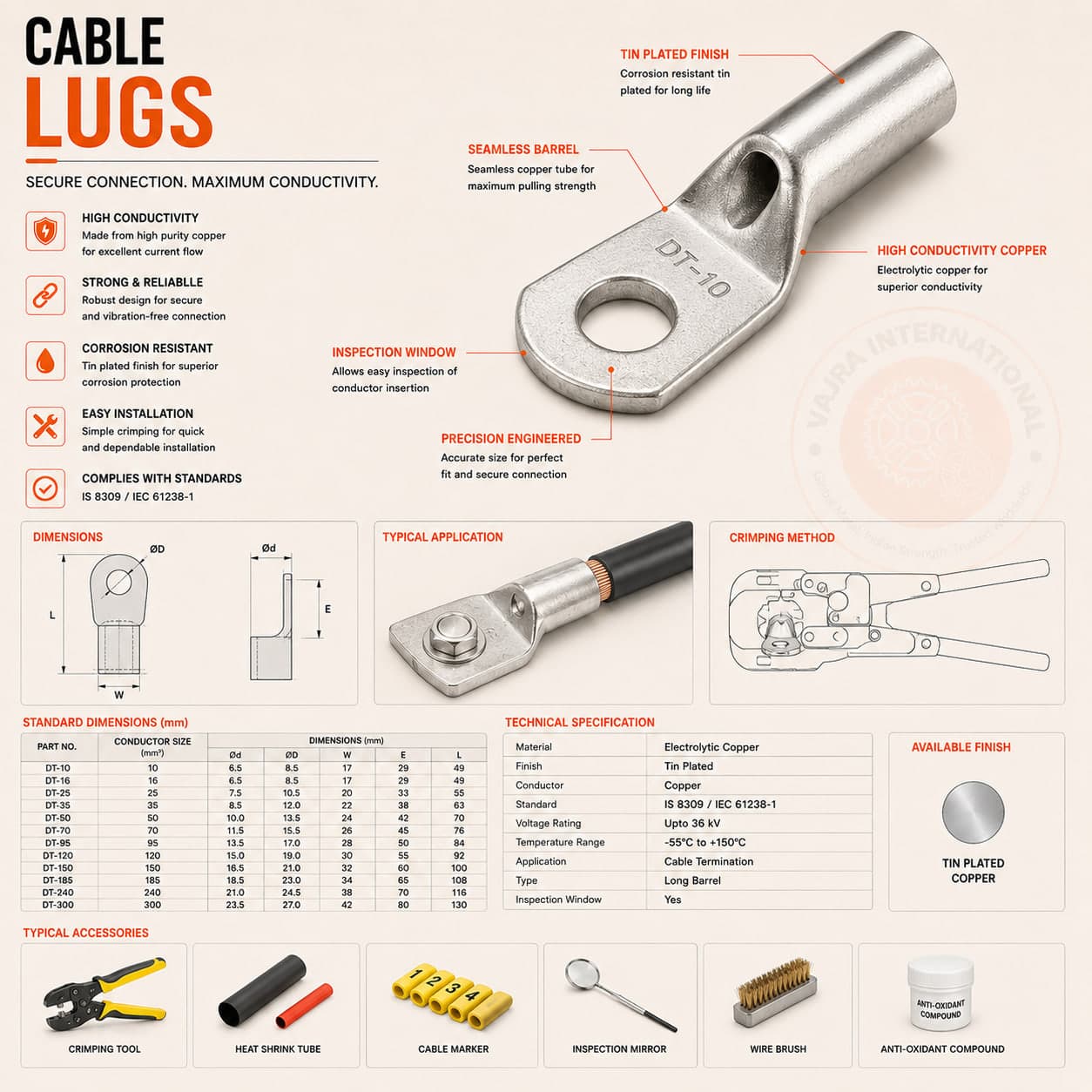
The tray has to be bonded back to the main earthing system at the supply end, and at intervals along a long run, with an earth conductor sized for the fault duty, the same adiabatic sizing that governs any protective conductor. Use a proper cable lug, crimped or bolted onto a cleaned, bare-metal contact on the tray, not screwed down onto a painted surface, and protect the contact against corrosion afterwards. Where a tray carries power and signal together, bonding also helps control electrical noise, but the safety earth comes first. Match the lug to the conductor size and the stud, because an undersized or loose lug is just one more joint waiting to fail.
Test it, and write the number down
None of this is real until it is measured. Test the earth continuity end to end with a low-resistance ohmmeter, not a pocket multimeter, looking for a low and consistent resistance along the run and a solid bond back to earth. IEC 61537 even classifies trays by their electrical continuity performance, so the tray you buy can be specified to carry earth rather than just assumed to. Do the test after the cables are pulled and the run is complete, because that is when joints get disturbed, and record the readings against the run so the next inspector has a baseline. A continuity test that nobody wrote down is a test that has to be done all over again.
A bolted joint is a mechanical joint, not an electrical one. If the tray is your earth path, jumper every joint, bond it back with a sized lug, and prove the continuity with an ohmmeter, because an earth people trust that is not actually there is the dangerous kind.
Using your cable tray as a parallel earth conductor? We supply trays to IEC 61537 with the continuity class stated, plus bonding jumpers, earth lugs and the sized earth conductors to tie the run back to your earthing system, all on one order.