
Earthing systems fail in two ways: they fail resistance tests because the electrode array is undersized relative to soil resistivity, and they pass resistance tests but fail safety because the grid was designed for ground resistance rather than for step and touch potential control. A substation earthing grid that measures 0.8 Ω total resistance can still produce a touch potential of 800 V at the fence during a phase-to-earth fault — enough to kill a worker standing at the gate. IS 3043:2018 addresses both failure modes through a two-part design process: ground resistance design and voltage distribution design. Most small and medium substations in India are designed and built using only the first part. This guide covers what IS 3043 actually requires and what the electrode and conductor selection implications are.
IS 3043:2018 — the scope and what changed in the 2018 revision
IS 3043 'Code of Practice for Earthing' was last substantially revised in 2018. The 2018 revision aligned IS 3043 more closely with IEEE Std 80-2013 (Guide for Safety in AC Substation Grounding) in its treatment of step and touch potential calculations, and updated the electrode sizing tables to reflect modern fault current levels at 33 kV and 132 kV substations under the growing renewable generation grid. Key changes: the 2018 revision added minimum conductor cross-section requirements as a function of earth fault current (previously these were often sourced from IEEE 80 by design engineers, not directly from IS 3043). It also clarified the connection requirements for equipment frames, transformer neutrals, and lightning protection system (LPS) bonding at the substation.
Soil resistivity — the one measurement that determines everything else
Soil resistivity (ρ) is the single most important input to an earthing system design. IS 3043 Cl. 4 requires a Wenner four-pin measurement at the actual substation site — desk-level estimates based on geological maps are not acceptable for design purposes. In practice: Wenner measurements should be taken in at least two orthogonal directions (north-south and east-west) to detect soil stratification or buried rock. Measurements at multiple electrode spacings (0.5 m through 5 m minimum) reveal layered soil profiles — an apparently good surface resistivity of 80 Ω·m can mask a deep rock layer at 5 m depth with 10,000 Ω·m resistivity, which completely changes the electrode design. A geotechnical report produced for foundation design purposes often includes Wenner data — confirm with the civil engineer whether the earthing design team can use this data or whether a separate measurement campaign is needed.
Fault current, conductor sizing and clearing time
IS 3043 Table 6 provides minimum conductor cross-sections for both GI strip and copper conductors as a function of the maximum earth fault current (Ig) and the fault clearing time (tc). The fault current flowing through the earthing system is not the full system fault current — a portion is absorbed by shield wires and remote earth electrodes. The earthing system must be sized for the portion flowing through the local grid (Ig), which the protection study must calculate for the specific substation configuration. For typical 33 kV substations in India: Ig ranges from 4 kA to 20 kA; tc from 0.2 s to 1.0 s depending on protection discrimination scheme. A 20 kA, 0.5 s clearing time substation requires a minimum 50×6 mm GI flat conductor or 95 mm² copper — not the 25×3 mm GI strip that is routinely specified on tender drawings without reference to the fault current.
Electrode selection: copper-bonded rod vs GI pipe vs flat grid
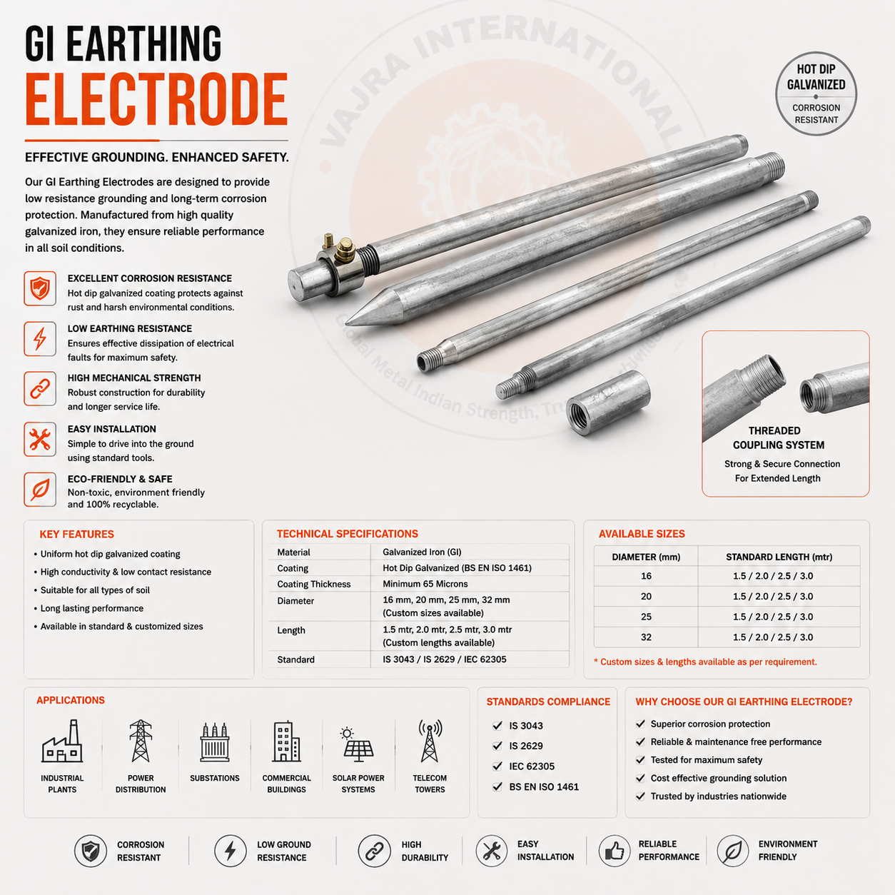
- Copper-bonded GI rods (IS 3043 Type): 14.2 mm or 16 mm diameter, 99.9% electrolytic tough pitch copper bonded to a high-tensile steel core by electrodeposition. Minimum copper layer 0.25 mm (250 µm). Resistance per metre: typically 0.8–1.2 Ω/m in 100 Ω·m soil. Drive depth: 2–5 m standard; deeper in high-resistivity soils. Life expectancy: 30+ years in typical Indian soils. The copper bonding provides cathodic protection — the copper sacrifices preferentially to protect the steel core. Preferred for distributed electrode networks in substations and industrial earthing grids.
- GI pipe electrodes (IS 3043 pipe type): 50 mm or 75 mm nominal bore, 2.5 m standard length, hot-dip galvanized. Resistance approximately 10–15% lower than equivalent-length rod due to larger diameter. Suitable for maintained earth pits where periodic inspection and backfill treatment (salt-charcoal-sand) is planned. Maintenance-friendly — access from grade level via the earth pit chamber. Less suited to deep driving in rocky soils.
- Horizontal flat strip grid: 25×3 mm, 25×6 mm, 40×6 mm or 50×6 mm GI flat strip buried at 0.5–0.8 m, forming the interconnecting grid between vertical electrodes. IS 3043 requires all grid conductors to be hot-dip galvanized to IS 4759 minimum 70 µm coating. Joints below grade must use exothermic welding (Cad-weld or equivalent) — bolted joints below grade corrode and increase resistance within 5 years.
- Copper strip grid: used in EHV substations (220 kV, 400 kV) and where soil corrosion is severe. Minimum 25×4 mm copper flat strip; 50×5 mm for high fault current systems. Copper strip costs 6–8× more than equivalent GI strip but eliminates long-term maintenance and resistance drift — appropriate for critical transmission assets.
Step and touch potential — the calculation most substation designs skip
Ground Potential Rise (GPR) is the voltage difference between the earthing grid and remote earth during a fault: GPR = Ig × Rg. A substation with Rg = 1 Ω and Ig = 20 kA has a GPR of 20,000 V — 20 kV above remote earth — during a fault. This 20 kV does not stay uniformly distributed across the earthing grid. Voltage gradients across the grid surface create step potentials (voltage between two points 1 m apart on the ground surface) and touch potentials (voltage between the grid/fence/structure and a point 1 m away). IEEE Std 80 and IS 3043 Annex provide the Km and Ki factors for calculating these voltages from grid geometry. The tolerable step potential for a 70 kg person at 1 Ω·m soil with 0.5 s fault clearing time is approximately 2,500 V; tolerable touch potential is approximately 640 V. A poorly designed grid produces step potentials that exceed 2,500 V at grid corners and periphery even when the total grid resistance is well under 1 Ω. Grid conductor spacing must be designed to keep mesh voltage below the tolerable limit — not just to achieve a target total resistance.
Specify the earthing electrode material and conductor section on the purchase order — not just 'as per IS 3043'. The fault current, clearing time and soil resistivity must be stated so the engineer can confirm the conductor cross-section is correct. A 25×3 mm GI strip costs 70% less than a 50×6 mm strip and carries less than 30% of the fault current capacity.
Need copper-bonded earthing electrodes, GI pipe earth electrodes or IS 3043 flat strip for a substation project? We supply all electrode types with EN 10204 Type 3.1 MTC from our Howrah facility — with project-specific sizing guidance included with the quotation.