
An IEC 61537 audit is not a specification review — it is a physical check that what was designed and specified is what was actually installed. The most common findings on Gulf, UK and Australian project audits are not failures in the tray itself but failures at the interface: the wrong support spacing, fill that crept past 75% during late cable pulls, coating damage at fixings, and missing bonding jumpers on long runs. This guide gives you the exact checklist and measurement procedures to audit an installed cable tray system against IEC 61537:2023.
What IEC 61537 requires and what it does not
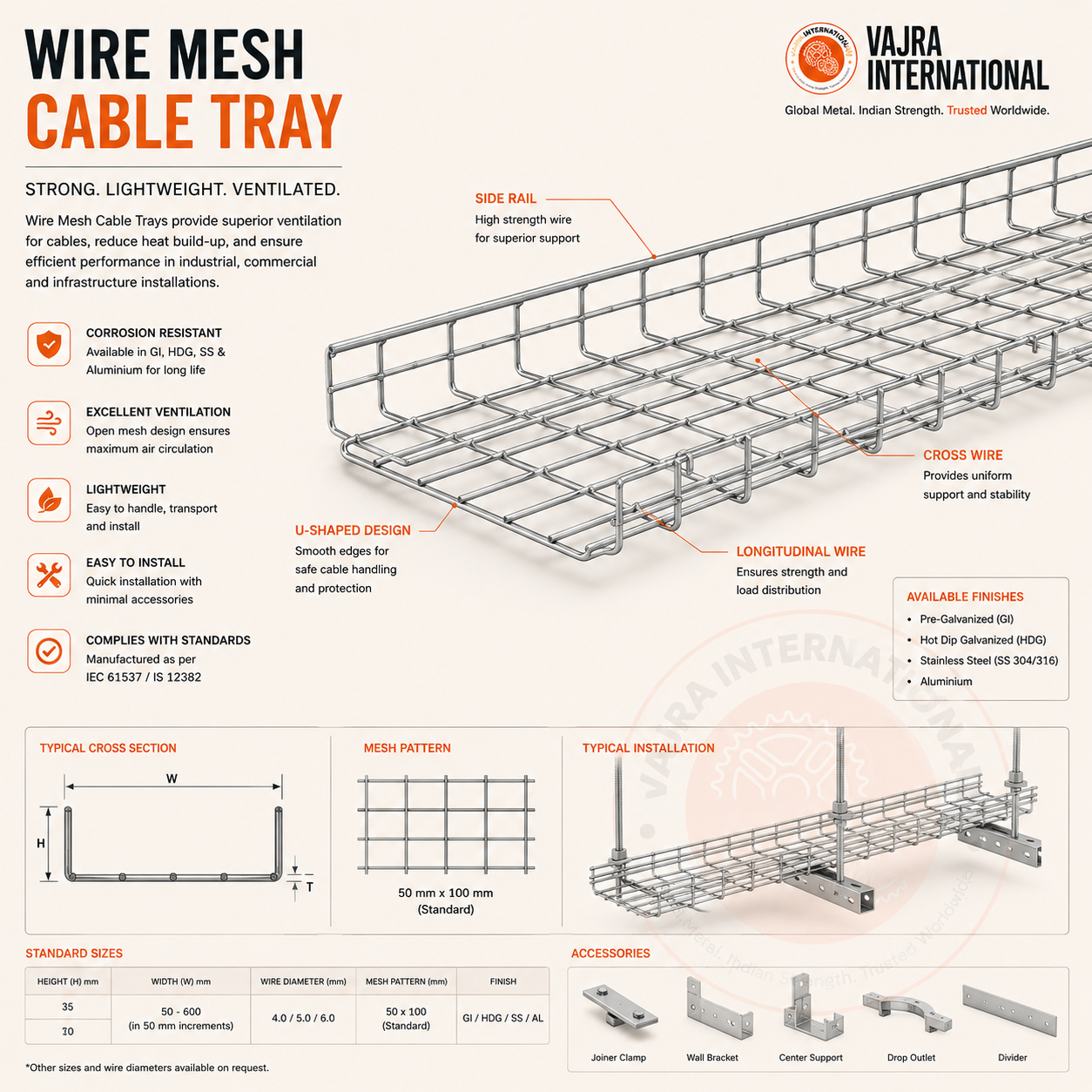
IEC 61537 is a product standard for cable trays — it governs how trays are classified, tested and marked at the factory. It does not govern installation directly (that is IEC 60364-5-52 for selection and installation, and the project's specific engineering standard for support details). However, IEC 61537 sets the classification framework that all installation specifications refer to: load class (C2 to C12 in kN/m), deflection limit (L/100 under working load), and fill ratio (≤75% of cross-section). An installation audit against IEC 61537 is therefore a check that: (a) the installed trays are actually the specified class, and (b) the installed conditions — span, fill, fixing — are within the boundary conditions the classification assumes.
Step 1 — Verify tray marking and identification
IEC 61537 Cl. 5.1 requires permanent marking on every tray. In practice, marking is on a sticker on the inner base of the tray — which gets covered once cables are installed. Audit before cable pulling where possible. If cables are already in, check a sample of unused or recently cut-off lengths in the contractor's store to verify the marking matches the specified class. Common substitution finding: Class 4 was specified and Class 2 was delivered. The marking is the only way to prove which class is installed without a laboratory test.
Step 2 — Coating thickness measurement
Zinc coating thickness is the most important determinant of long-term corrosion resistance — and the most commonly under-specified at installation stage. A DFT (dry film thickness) gauge measures in seconds and gives you a 5-point average per tray. The critical measurement points: top flanges (outer face), tray base (under surface, exposed to moisture drainage), and at a bolt hole. A reading below 60 µm at a bolt hole on a coastal project is a major NCR — that location will rust through in 3–5 years regardless of the tray surface condition.
- Indoor, controlled environment: minimum 45 µm per ISO 1461 thickness grade for <1.5 mm section
- Outdoor, industrial atmosphere (C3): minimum 70 µm average
- Coastal, within 5 km of sea or chemical atmosphere (C4/C5): minimum 85 µm average, 73 µm minimum single reading
- Splash zone, chemical plants (C5-M or CX): 100 µm minimum or stainless steel
Step 3 — Fill ratio calculation
The 75% fill rule is consistently violated on projects where cables were added late — after the tray was sized for the original cable schedule. The calculation: sum all installed cable cross-sections (use π/4 × OD² for circular cables, actual cross-section for flat cables) and compare to the tray's internal cross-section (clear width × usable depth, deducting the rung depth for ladder trays). If the result exceeds 75%, the tray run must be extended with a parallel tray, or cables must be relocated. Do not accept 'it's close enough' — IEC 61537 Cl. 5.5 is a hard limit for both thermal and structural reasons.
Step 4 — Support span verification
Span is the most commonly overlooked parameter in installation audits. A Class 4 tray at 1 m span can carry 4 kN/m with minimal deflection. The same Class 4 tray at 3.5 m span with the same load exceeds both the deflection limit (>L/100) and the structural capacity. Measure the actual cantilever or trapeze support spacing using a tape measure — do not rely on as-built drawings. Record any span that exceeds the manufacturer's load table value for the installed load class and actual span. Common finding: supports were originally at 3 m, and then the last bay of a run has a 4–5 m gap due to a structural obstruction — unrecorded in the as-built.
Step 5 — Electrical continuity testing
If the cable tray is used as a protective conductor (earthing) route — which is common on industrial and substation installations — IEC 61537 Cl. 8.3 sets a 0.1 Ω maximum resistance per joint. Test with a low-resistance ohmmeter (Ductor, Megger DLRO, or similar) at a DC test current of minimum 100 mA to avoid contact resistance masking the reading. Test across the splice plate, not across the bonding jumper. Most failed joint tests result from: serrated washers missing or not biting into the tray surface, painted tray surfaces (paint is non-conductive — requires star washers or bonding jumpers), or corroded splice plates on older installations.
A tray run used as a protective conductor with high joint resistance is a hidden safety hazard — it will fail to carry fault current and may cause a dangerous touch voltage rather than tripping the protective device. This is the audit finding that requires an immediate stop-work notice, not a 30-day NCR close-out.
NCR classification and close-out
Structure your NCRs in three categories: (1) Safety-critical — fill > 75% on a live power cable run, joint resistance > 0.1 Ω on earthing runs, span > 150% of rated span. These require stop-work and immediate remediation. (2) Major — coating below minimum, missing tray marking, unsupported splice joints, covers missing on vertical runs. These require remediation before commissioning sign-off. (3) Minor — inconsistent cover type, cable ties not at rated spacing, cosmetic damage. These can be tracked on a punch list for close-out before project handover.
Need cable trays built to IEC 61537 with pre-punched HDG fixings, coating inspection reports and EN 10204 Type 3.1 MTC? We supply from our Howrah facility to projects across the Gulf, UK, Australia and East Africa.